Shifter
A shifter is a combinational logic circuit which shifts the bits of a value one place to the left or right. The shifter's function is similar to that of a bidirectional shift register. However, the register is a sequential logic circuit and this makes it unsuitable to be used in a function unit.
The basic n-bit shifter design comprises n 2-to-4 multiplexers, one multiplexer per input bit.
If we have an n-bit input A, then the multiplexer for bit m is configured as follows:
| Input line | Input Value |
|---|---|
0 |
A[m] |
1 |
A[m+1] |
2 |
A[m-1] |
3 |
0 (Unused) |
The table below shows the meaning of the selection binary code input to the multiplexer in such a configuration:
| Selection code | Meaning |
|---|---|
00 |
No shift |
01 |
Shift right |
10 |
Shift left |
11 |
Zero output |
The only problem with this is what happens at the most and least significant bits.
Upon a left shift, we need to give an input to tell the shifter what the new least significant bit should be as there is no
A[-1].
Let's call this L.
Similarly, Upon a right shift, we need to give an input to tell the shifter what the new most significant bit should be as there is no
A[n+1].
Let's call this R.
This is probably easier to understand if we rewrite the multiplexer configuration table for the least significant bit case (bit 0):
| Input line | Input Value |
|---|---|
0 |
A[0] |
1 |
A[1] |
2 |
L |
3 |
0 (Unused) |
And the following table is for the most significant bit (bit n):
| Input line | Input Value |
|---|---|
0 |
A[n] |
1 |
R |
2 |
A[n-1] |
3 |
0 (Unused) |
Example
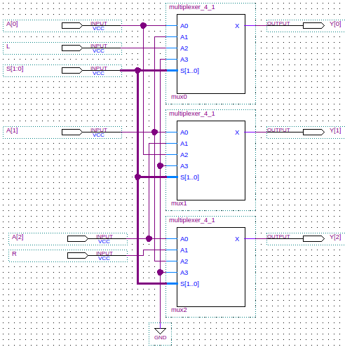
The schematic for a shifter is shown below. To save space, a 3-bit shifter design is shown.
Here the shifted output is the 3-bit value Y.
The 2-bit input value S is the multiplexer selector.
Verilog
Below is the Verilog code for a structural model of a 16-bit shifter. The code is also shown for the multiplexer.
module shifter_16(Y, A, S, L, R);
   output [15:0] Y;  // The shifted result.
   input [15:0]  A;  // The value to be shifted.
   input [1:0] 	 S;  // The direction of the shift.
   input 	 L;  // The leftmost bit to shift in.
   input 	 R;  // The rightmost bit to shift in.

   multiplexer_4_1 #(1) mux0(Y[0], A[0], A[1], L, 1'b0, S[1], S[0]);
   multiplexer_4_1 #(1) mux1(Y[1], A[1], A[2], A[0], 1'b0, S[1], S[0]);
   multiplexer_4_1 #(1) mux2(Y[2], A[2], A[3], A[1], 1'b0, S[1], S[0]);
   multiplexer_4_1 #(1) mux3(Y[3], A[3], A[4], A[2], 1'b0, S[1], S[0]);
   multiplexer_4_1 #(1) mux4(Y[4], A[4], A[5], A[3], 1'b0, S[1], S[0]);
   multiplexer_4_1 #(1) mux5(Y[5], A[5], A[6], A[4], 1'b0, S[1], S[0]);
   multiplexer_4_1 #(1) mux6(Y[6], A[6], A[7], A[5], 1'b0, S[1], S[0]);
   multiplexer_4_1 #(1) mux7(Y[7], A[7], A[8], A[6], 1'b0, S[1], S[0]);
   multiplexer_4_1 #(1) mux8(Y[8], A[8], A[9], A[7], 1'b0, S[1], S[0]);
   multiplexer_4_1 #(1) mux9(Y[9], A[9], A[10], A[8], 1'b0, S[1], S[0]);
   multiplexer_4_1 #(1) mux10(Y[10], A[10], A[11], A[9], 1'b0, S[1], S[0]);
   multiplexer_4_1 #(1) mux11(Y[11], A[11], A[12], A[10], 1'b0, S[1], S[0]);
   multiplexer_4_1 #(1) mux12(Y[12], A[12], A[13], A[11], 1'b0, S[1], S[0]);
   multiplexer_4_1 #(1) mux13(Y[13], A[13], A[14], A[12], 1'b0, S[1], S[0]);
   multiplexer_4_1 #(1) mux14(Y[14], A[14], A[15], A[13], 1'b0, S[1], S[0]);
   multiplexer_4_1 #(1) mux15(Y[15], A[15], R, A[14], 1'b0, S[1], S[0]);
endmodule // shifter_16

module multiplexer_4_1(X, A0, A1, A2, A3, S1, S0);
   parameter WIDTH=16;     // How many bits wide are the lines

   output [WIDTH-1:0] X;   // The output line

   input [WIDTH-1:0]  A3;  // Input line with id 2'b11
   input [WIDTH-1:0]  A2;  // Input line with id 2'b10
   input [WIDTH-1:0]  A1;  // Input line with id 2'b01
   input [WIDTH-1:0]  A0;  // Input line with id 2'b00
   input 	      S0;  // Least significant selection bit
   input 	      S1;  // Most significant selection bit

   assign X = (S1 == 0
	       ? (S0 == 0
		  ? A0       // {S1,S0} = 2'b00
		  : A1)      // {S1,S0} = 2'b01
	       : (S0 == 0
		  ? A2       // {S1,S0} = 2'b10
		  : A3));    // {S1,S0} = 2'b11
endmodule // multiplexer_4_1
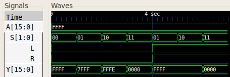
When given test inputs, the 16-bit shifter generated the following waveform:
References
Mano, M. Morris, and Kime, Charles R. Logic and Computer Design Fundamentals. 2nd Edition. Prentice Hall, 2000.