Multiplier (Simple)
A multiplier is an arithmetic combinational logic circuit which multiplies a M-bit binary number with an N-bit binary number and outputs the (M+N)-bit binary product. The method shown here is probably the simplest of all multiplier designs.
In school you were probably taught to multiply multi-digit numbers by breaking the problem down into simpler single-digit multiplications. For example, if we were to multiply 123 by 32, then we would no doubt write down something like this:
      123
     x 32
     ----
(x2)  246
(x3) 369
     ----
(+)  3936
Here we have turned the multi-digit multiplication into two single-digit multiplications and an addition of the intermediate products. A digital circuit can be built to perform the same steps in parallel (i.e., a combinational, not a sequential step-by-step, circuit). The key to binary multiplication is the realisation that the multiplication of two bits is performed by a simple AND gate. To multiply a M-bit number by a single bit, in order to generate an intermediate product, we would need M AND gates. An adder, such as a ripple carry adder can be used to perform the summation of the intermediate products. When we multiply a M-bit number by an N-bit number we would need N-1 such adders. As for the final result, it will need at most M+N bits for storage.
Example
As an example, consider the multiplication of two 3-bit numbers, A and B, giving the product P. We'll write P5 for bit 5 of P, and A0B1 for bit 0 of A multiplied by bit 1 of B. Bit 0 will be the least significant bit. The plan of action would be:
                A2  A1   A0
            x   B2  B1   B0
            ---------------
             A2B0 A1B0 A0B0    (P0 = A0B0)
     +  A2B1 A1B1 A0B1
    ----------------------
     S3   S2   S1   S0         (P1 = S0, S3 is the carry out of the above addition)
 + A2B2 A1B2 A0B2
------------------
 P5   P4   P3  P2              (P5 is the carry out of the above addition)
From this we can see how we should configure our two ripple carry adders and nine AND gates.
Verilog
The following Verilog code implements a 4-bit multiplier. The code for the ripple carry adder and the full adder is also shown for completeness.
module multiplier(P, A, B);
   output [7:0] P; // The 8-bit product.
   input [3:0] 	A; // The 4-bit multiplicand.
   input [3:0] 	B; // The 4-bit multiplier.

   wire [3:0] 	Augend0; // Input to first intermediate addition.
   wire [3:0] 	Addend0; // Input to first intermediate addition.
   wire [3:0] 	Sum0;    // First intermediate sum.
   wire 	Carry0;  // Carry output of first intermediate addition.
   wire [3:0] 	Addend1; // Input to second intermediate addition.
   wire [3:0] 	Augend1; // Input to second intermediate addition.
   wire [3:0] 	Sum1;    // Second intermediate sum.
   wire 	Carry1;  // Carry output of second intermediate addition.
   wire [3:0] 	Augend2; // Input to last addition.
   wire [3:0] 	Addend2; // Input to last addition.

   //
   // Augend0 = (A * B[0]) rshift 1
   //
   and(P[0], A[0], B[0]);        // Bit 0 goes straight to P.
   and(Augend0[0], A[1], B[0]);
   and(Augend0[1], A[2], B[0]);
   and(Augend0[2], A[3], B[0]);
   assign Augend0[3] = 0;

   //
   // Addend0 = A * B[1]
   //
   and(Addend0[0], A[0], B[1]);
   and(Addend0[1], A[1], B[1]);
   and(Addend0[2], A[2], B[1]);
   and(Addend0[3], A[3], B[1]);

   ripple_carry_adder rc0(Sum0, Carry0, Augend0, Addend0); // {Carry0, Sum0} = Augend0 + Addend0
   assign P[1] = Sum0[0];

   //
   // Augend1 = (Augend0 + Addend0) rshift 1
   //
   assign Augend1[0] = Sum0[1];
   assign Augend1[1] = Sum0[2];
   assign Augend1[2] = Sum0[3];
   assign Augend1[3] = Carry0;

   //
   // Addend1 = A * B[2]
   //
   and(Addend1[0], A[0], B[2]);
   and(Addend1[1], A[1], B[2]);
   and(Addend1[2], A[2], B[2]);
   and(Addend1[3], A[3], B[2]);

   ripple_carry_adder rc1(Sum1, Carry1, Augend1, Addend1); // {Carry1, Sum1} = Augend1 + Addend1
   assign P[2] = Sum1[0];

   //
   // Augend2 = (Augend1 + Addend1) rshift 1
   //
   assign Augend2[0] = Sum1[1];
   assign Augend2[1] = Sum1[2];
   assign Augend2[2] = Sum1[3];
   assign Augend2[3] = Carry1;

   //
   // Addend2 = A * B[3]
   //
   and(Addend2[0], A[0], B[3]);
   and(Addend2[1], A[1], B[3]);
   and(Addend2[2], A[2], B[3]);
   and(Addend2[3], A[3], B[3]);

   ripple_carry_adder rc2(P[6:3], P[7], Augend2, Addend2); // {P[7], P[6], P[5], P[5], P[3]} = Augend2 + Addend2
endmodule // multiplier


module ripple_carry_adder(S, C, A, B);
   output [3:0] S;  // The 4-bit sum.
   output 	C;  // The 1-bit carry.
   input [3:0] 	A;  // The 4-bit augend.
   input [3:0] 	B;  // The 4-bit addend.

   wire 	C0; // The carry out bit of fa0, the carry in bit of fa1.
   wire 	C1; // The carry out bit of fa1, the carry in bit of fa2.
   wire 	C2; // The carry out bit of fa2, the carry in bit of fa3.

   full_adder fa0(S[0], C0, A[0], B[0], 0);    // Least significant bit.
   full_adder fa1(S[1], C1, A[1], B[1], C0);
   full_adder fa2(S[2], C2, A[2], B[2], C1);
   full_adder fa3(S[3], C, A[3], B[3], C2);    // Most significant bit.
endmodule // ripple_carry_adder

module full_adder(S, Cout, A, B, Cin);
   output S;
   output Cout;
   input  A;
   input  B;
   input  Cin;

   wire   w1;
   wire   w2;
   wire   w3;
   wire   w4;

   xor(w1, A, B);
   xor(S, Cin, w1);
   and(w2, A, B);
   and(w3, A, Cin);
   and(w4, B, Cin);
   or(Cout, w2, w3, w4);
endmodule // full_adder
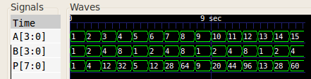
When given test inputs, the 4-bit multiplier generated the following waveform (values in decimal):
References
Mano, M. Morris, and Kime, Charles R. Logic and Computer Design Fundamentals. 2nd Edition. Prentice Hall, 2000.