LCR Series Circuit
The following is a LCR series circuit (L stands for inductor, C for capacitor, and R for resistor).
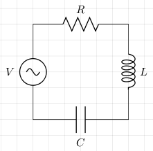
Let the instantaneous voltages for L, C, and R, be vL, vC, and vR respectively, and let the instantaneous supply voltage be v. According Kirchhoff's voltage law
v=vL+vC+vR
Since the voltages are out of phase we cannot add the peaks or root mean square (RMS) of
the voltages.
The current through each component is the same.
The peak or RMS voltage through the resistor, VR is in phase with the current.
The peak or RMS voltage across the inductor, VL, precedes VR by π/2.
The peak or RMS voltage across the capacitor, VC, follows VR by π/2.
We can draw the vector sum, of peak or RMS voltages,
VT = ,
as shown in the following graph:
VR+VL+VC
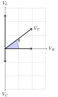
The angle θ is the phase of the peak or RMS voltage with respect to the peak or RMS current.
This angle is calculated as follows:
tan θ = (VL-VC)/VR
As an alternative to the vector approach, this can also be expressed as the complex number
VT = VR+j(VL-VC)
Here j and not i is used as the value of √-1 as i is used for current.
References
Fischer-Cripps. A.C., The Electronics Companion. Institute of Physics, 2005.