Carry Select Adder
A carry select adder is an arithmetic combinational logic circuit which adds two N-bit binary numbers and outputs their N-bit binary sum and a 1-bit carry. This is no different from a ripple carry adder in function, but in design the carry select adder does not propagate the carry through as many full adders as the ripple carry adder does. This means that the time to add two numbers should be shorter. It seems this optimisation was used by Charles Babbage in his design for the Analytical Engine.
The idea behind a N-bit carry select adder is to avoid propagating the the carry from bit to bit in sequence.
If we have two adders in parallel: one with a carry input of 0, the other with a carry input of 1,
then we could use the actual carry input generated to select between the outputs of the two parallel adders.
This means all adders could be performing their calculations in parallel.
Having two adders for each result bit is quite wasteful so we could configure the N-bit adder to use 2*N/M-1 M-bit ripple carry adders in
parallel.
Note that the adder for the least significant bits will always have a carry input of 0 so no parallel addition is needed
in this case.
Example
As an example, an 8-bit carry select adder could comprise three 4-bit ripple carry adders: one would calculate the sum and carry for the low nibble sum (bits 0 to 3), and the other two would calculate the high nibble sum and carry (bits 4 to 7). All adders would calculate in parallel. We could then use the low nibble carry output as a selector for a multiplexer that would choose the correct results from the high nibble sums and carries.
Verilog
The following Verilog code shows an 8-bit carry select adder. The code for ripple carry adder, the full adder, and the multiplexer is also shown for completeness.
module carry_select_adder(S, C, A, B);
   output [7:0] S;   // The 8-bit sum.
   output 	C;   // The 1-bit carry.
   input [7:0] 	A;   // The 8-bit augend.
   input [7:0] 	B;   // The 8-bit addend.

   wire [3:0] 	S0;   // High nibble sum output with carry input 0.
   wire [3:0] 	S1;   // High nibble sum output with carry input 1.
   wire 	C0;   // High nibble carry output with carry input 0.
   wire 	C1;   // High nibble carry output with carry input 1.
   wire 	Clow; // Low nibble carry output used to select multiplexer output.

   ripple_carry_adder rc_low_nibble_0(S[3:0], Clow, A[3:0], B[3:0], 0);  // Calculate S low nibble.
   ripple_carry_adder rc_high_nibble_0(S0, C0, A[7:4], B[7:4], 0);       // Calcualte S high nibble with carry input 0.
   ripple_carry_adder rc_high_nibble_1(S1, C1, A[7:4], B[7:4], 1);       // Calcualte S high nibble with carry input 1.
   multiplexer_2_1 #(4) muxs(S[7:4], S0, S1, Clow);  // Clow selects the high nibble result for S.
   multiplexer_2_1 #(1) muxc(C, C0, C1, Clow);       // Clow selects the carry output.
endmodule // carry_select_adder

module ripple_carry_adder(S, C, A, B, Cin);
   output [3:0] S;   // The 4-bit sum.
   output 	C;   // The 1-bit carry.
   input [3:0] 	A;   // The 4-bit augend.
   input [3:0] 	B;   // The 4-bit addend.
   input 	Cin; // The carry input.

   wire 	C0; // The carry out bit of fa0, the carry in bit of fa1.
   wire 	C1; // The carry out bit of fa1, the carry in bit of fa2.
   wire 	C2; // The carry out bit of fa2, the carry in bit of fa3.

   full_adder fa0(S[0], C0, A[0], B[0], Cin);    // Least significant bit.
   full_adder fa1(S[1], C1, A[1], B[1], C0);
   full_adder fa2(S[2], C2, A[2], B[2], C1);
   full_adder fa3(S[3], C, A[3], B[3], C2);    // Most significant bit.
endmodule // ripple_carry_adder

module full_adder(S, Cout, A, B, Cin);
   output S;
   output Cout;
   input  A;
   input  B;
   input  Cin;

   wire   w1;
   wire   w2;
   wire   w3;
   wire   w4;

   xor(w1, A, B);
   xor(S, Cin, w1);
   and(w2, A, B);
   and(w3, A, Cin);
   and(w4, B, Cin);
   or(Cout, w2, w3, w4);
endmodule // full_adder

module multiplexer_2_1(X, A0, A1, S);
   parameter WIDTH=16;     // How many bits wide are the lines

   output [WIDTH-1:0] X;   // The output line

   input [WIDTH-1:0]  A1;  // Input line with id 1'b1
   input [WIDTH-1:0]  A0;  // Input line with id 1'b0
   input 	      S;  // Selection bit

   assign X = (S == 1'b0) ? A0 : A1;
endmodule // multiplexer_2_1
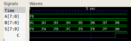
When given test inputs, the 8-bit carry select adder generated the following waveform:
References
Harrison, John. Handbook of Practical Logic and Automated Reasoning. Cambridge, 2009.